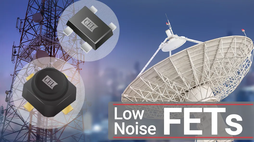


In a satellite LNB, the first amplifier stage sets most of the receiver’s noise figure. CEL’s low noise GaAs FETs put 0.30 dB typical at 12 GHz and 0.55 dB at 20 GHz in plastic packages, with a 2.0 x 1.25 mm option for the later stages. This post lists the parts, where each one goes in the chain, and what the datasheets guarantee.
Full tables, datasheets and S-parameters are on the Low Noise Devices page.
Why the First Stage Matters
The Friis equation divides each later stage’s noise by the gain in front of it. Take a CE3512K2 first stage (0.30 dB NF, 13.7 dB gain) followed by a CE3514M4 (0.42 dB NF). The second stage adds about 0.02 dB, for a total near 0.32 dB. Swap the order and you give up about 0.1 dB.
These are device typicals. Input matching and board loss in front of the first FET add directly to the noise figure, so layout ahead of stage one matters as much as part choice.
12 GHz Ku-Band LNB Parts
| Part | Package | NF typ / max (dB) | Gain typ (dB) | Bias |
|---|---|---|---|---|
| CE3512K2 | K2 Micro-X, 2.6 x 2.6 x 1.5 mm | 0.30 / 0.50 | 13.7 | 2 V, 10 mA |
| CE3522K2 | K2 Micro-X, 2.6 x 2.6 x 1.5 mm | 0.32 / 0.52 | 14.0 | 2 V, 10 mA |
| CE7613M4 | M4, 2.0 x 1.25 x 0.6 mm | 0.35 / 0.53 | 14.1 | 2 V, 10 mA |
| CE3514M4 | M4, 2.0 x 1.25 x 0.6 mm | 0.42 / 0.62 | 12.2 | 2 V, 10 mA |
All values at 12 GHz. The CE3512K2 and CE3522K2 datasheets list them as suited to the first stage of a Ku-band LNB. CEL’s reference chain uses the CE3512K2 first and the CE3514M4 second. The CE3514M4 datasheet also lists it for the mixer stage.
The CE3522K2 trades 0.02 dB of noise figure for 0.3 dB more gain than the CE3512K2. The CE7613M4 gets within 0.05 dB of the CE3512K2 in the smaller M4 package, with the highest gain of the four.
20 GHz LNB Parts
| Part | Package | NF typ / max (dB) | Gain typ (dB) | Bias |
|---|---|---|---|---|
| CE3520K3 | K3 Micro-X, 2.6 x 2.6 x 1.5 mm | 0.55 / 0.80 at 20 GHz, 0.80 typ at 24 GHz | 13.8 at 20 GHz, 13.9 at 24 GHz | 2 V, 10 mA |
| CE3521M4 | M4, 2.0 x 1.25 x 0.6 mm | 0.70 / 1.05 | 11.9 | 2 V, 10 mA |
CEL’s reference 20 GHz LNB uses the CE3520K3 in the first stage and the CE3521M4 in the second and third. One limit to know: the CE3520K3’s 24 GHz figures are typical only and not tested on production parts. The 20 GHz figures are 100% tested.
GNSS and L-Band
| Part | Package | NF typ (dB) | Gain typ (dB) | P1dB (dBm) | Bias |
|---|---|---|---|---|---|
| CA3509M4 | M4, 2.0 x 1.25 x 0.6 mm | 0.40 | 17.0 | 12.0 | 3 V, 15 mA |
The CA3509M4 is an LNA IC, not a discrete FET. It has on-chip bias and ESD protection and is specified at 1.575 GHz for GPS, GLONASS, BeiDou and Galileo antennas, as well as satellite radio. Use it in an active GNSS antenna, not in a Ku or Ka LNB.
K2, K3 or M4
The K2 and K3 Micro-X packages are hollow, air-cavity plastic. They carry the lowest noise figures in the lineup. The M4 is a flat-lead 4-pin super minimold at 2.0 x 1.25 x 0.6 mm, about a third of the K2 footprint. A common split is K2 or K3 for stage one and M4 for the stages after it, where a few tenths of a dB cost little.
The FETs share a recommended operating range of 1 to 3 V drain voltage and 5 to 15 mA drain current, with a 4 V absolute maximum. The K2 and K3 packages have their own flux and cleaning guidance, listed below.
Replacing Renesas Parts
CEL offers these as drop-in alternatives to discontinued Renesas devices:
| CEL part | Replaces |
|---|---|
| CE3512K2 | NE3210S01, NE3511S02, NE3512S02, NE3516S02, NE4210S01 |
| CE3514M4 | NE3503M04, NE3513M04 |
| CE3520K3 | NE3514S02, NE3517S03, NE3520S03 |
| CE3521M4 | NE3521M04 |
Check the pinout and footprint against your existing layout, and re-tune the match from the CEL S-parameters before you commit a build.
Design Resources
- Using Low Noise Block in Satellite Applications, a Ku-band LNA design walkthrough with the CE3512K2
- Product Brief: GaAs FETs (PDF)
- K2, K3, M4 Layout Guide (PDF)
- CA3509M4 Evaluation Board (PDF)
- Modelithics Equivalent Circuit Models
- Recommended Soldering Conditions: Partial Heating (PDF)
- Recommended Soldering Conditions: Reflow (PDF)
- K2 and K3 Recommended Soldering Flux and Cleaning Conditions (PDF)
- RF Components Selection Guide (PDF)
S-parameter files for each FET are on the Low Noise Devices page. Parts are stocked at DigiKey and Mouser.
Questions on stage placement or matching? Use the form below and a CEL engineer will follow up.